Logic Gates
Logic Gate
A logic gate is an electronic circuit that operates on one or more input signals to produce an output signal. The logic gate is used for binary operation and is the basic component of a digital computer. The function of gate is expressed by means of an algebraic expression.
The different types of logical gates are:
Basic Logic Gates:
• AND Gate
a. AND gate is an electronic circuit, which produces low (0) output when any of the input or all the input are low (0), otherwise the output will be high (1). It has two or more inputs and single output.
b. Graphical / Logical symbols :

c. Algebric expression/ logical function:
Y = A.B
where Y is output, A and B are inputs and (.) is AND operation .
d. Truth Table :
| Input | Output |
|---|---|
| A B | Y= A.B |
| 0 0 | 0 |
| 0 1 | 0 |
| 1 0 | 0 |
| 1 1 | 1 |
e. Venn diagram

• OR Gate
a. OR gate is an electronic circuit, which produces high (1) output when any of the input or all the inputs are high (1), otherwise, the output will be low (0). It has two or more inputs and single output .
b. Graphical / Logical symbols :

c. Algebric expression/ logical function:
Y = A+B
where Y is output, A and B are inputs and (+) is OR operation .
d. Truth Table :
| Input | Output |
|---|---|
| A B | Y= A+B |
| 0 0 | 0 |
| 0 1 | 1 |
| 1 0 | 1 |
| 1 1 | 1 |
e. Venn diagram

• NOT Gate
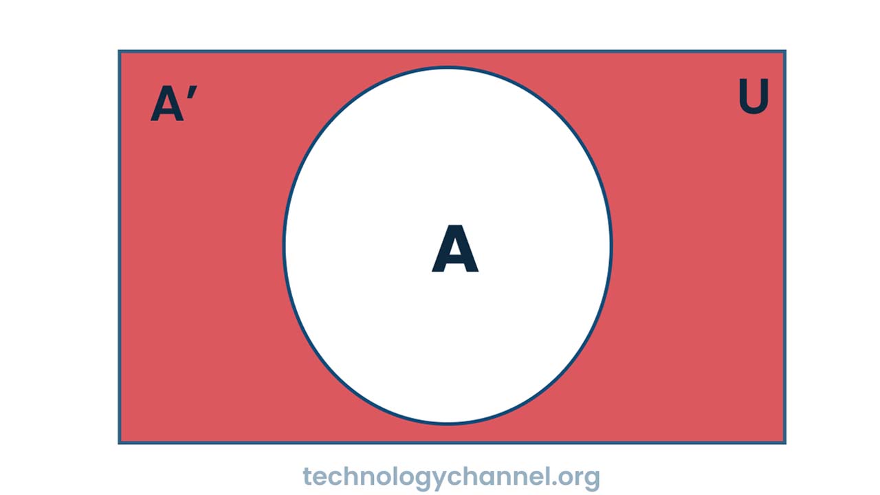
a. NOT gate is an electronic circuit , which produces high (1) output when the input low (0), and low output when the input is high. It has single input and single output.
b. Graphical / Logical symbols :

c. Algebric expression/ logical function:
Y = A’
Where Y is the output, A input and (’) is NOT operation .
d. Truth Table :
| Input | Output |
|---|---|
| A | F= A' |
| 0 | 1 |
| 1 | 0 |
e. Venn diagram
Universal Gates:
• NAND Gate
a. It is combination of AND and NOT gate.
b. Graphical / Logical symbol:

c. Algebric expression/ logical function:
Y =( A.B )’
where Y is output, A and B are inputs.
d. Truth Table :
| Input | Output | |
|---|---|---|
| A B | Y=A.B | Y=(A.B)' |
| 0 0 | 0 | 1 |
| 0 1 | 0 | 1 |
| 1 0 | 0 | 1 |
| 1 1 | 1 | 0 |
e. Venn diagram

Difference between AND & NAND gate
The Differences between AND & NAND gate are:
| AND Gate | NAND Gate |
|---|---|
| • AND gate produce 0 output when any of the input or all the input are 0, otherwise output will be 1. | • NAND gate produce 0 output when all the input are 1, otherwise output will be 1. |
| • Algebraic expression is Y = A.B | • Algebraic expression is Y=(A.B)’ |
| • AND gate is only AND gate. | • NAND gate is the combination of AND and NOT gate. |
• NOR Gate.
a. It is combination of OR and NOT gate.
b. Graphical / Logical symbol:

c. Algebric expression/ logical function:
Y = (A+B)’
where Y is output, A and B are inputs .
d. Truth Table :
| Input | Output | |
|---|---|---|
| A B | Y=A+B | Y=(A+B)' |
| 0 0 | 0 | 1 |
| 0 1 | 1 | 0 |
| 1 0 | 1 | 0 |
| 1 1 | 1 | 0 |
e. Venn diagram

Combinational Gates:
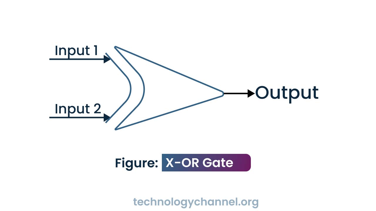
• X-OR Gate,
a. The exclusive OR gate is circuit which will give a high output if either, but not both, of its two inputs are high.
b. Graphical / Logical symbol:
c. Algebric expression/ logical function:
Y =( A’B+AB’ )
where Y is output, A and B are inputs.
d. Venn diagram

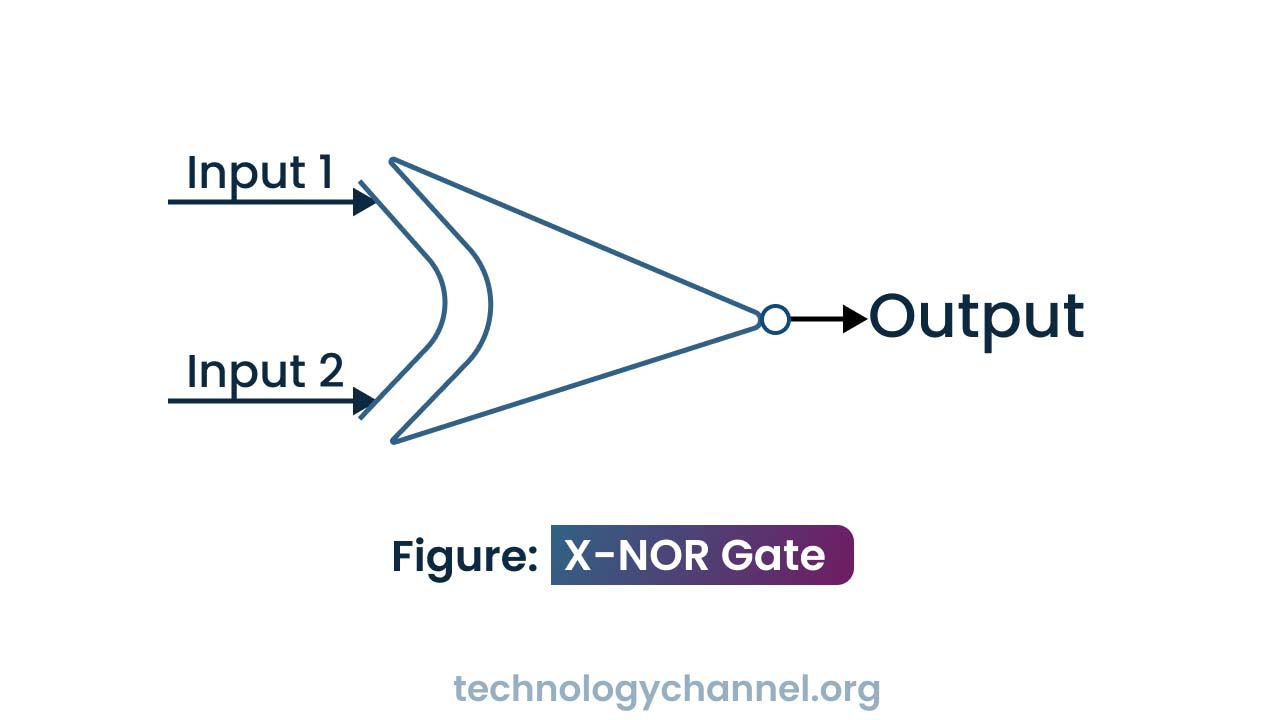
• X-NOR Gate
a. The exclusive NOR gate is circuit which will give a high output when all inputs are same either high(1) or low(0).
b. Graphical / Logical symbol:
c. Algebric expression/ logical function:
Y =( A.B+A’B’ ) or Y =(A’B+AB’)’
where Y is output, A and B are inputs.
d. Venn diagram

Truth table for ‘XOR’ and ‘XNOR’ operation
| Input | Output | |
|---|---|---|
| A B | X-OR = F=(A’B+AB’) | X-NOR = F =(A.B+A’B’) |
| 0 0 | 0 | 1 |
| 0 1 | 1 | 0 |
| 1 0 | 1 | 0 |
| 1 1 | 0 | 1 |